Lathes Part 3:
Building a “Not So Great Wheel”
Lathes Part 3:
Building a “Not So Great Wheel”
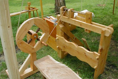
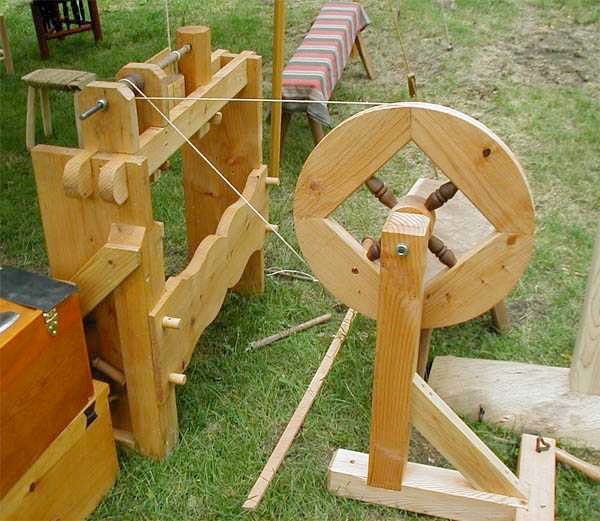
In the pictures, the drive cord runs to the same headstock I use for the flywheel, but it can also be run directly to the work piece. In that configuration, the workpiece can simply be mounted between two centers, also greatly simplifying the configuration, though then one must cut around the drive cord.
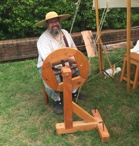
At the event where I took these pictures, a young boy of no more than 6 or 7 and his somewhat younger sister came up to see the machine. I invited them to try turning the wheel, which the boy found fascinating. After a few minutes, his father asked if he was getting tired, but he assured he was doing fine. He just had to see what I was going to make. After a few more minutes I released him from his service (his parents were getting restless), and gave him groat for his service, explaining that that was what money looked like 400 years ago. His eyes got really wide and he thanked me, then strolled off with this family. For that experience, this project was worth the effort.
Having used a flywheel treadle lathe for a while, for demonstrations and furniture turning, it became apparent that there are some drawbacks to this type of motive power. While it does have the advantage of continuous rotation (spring pole purists will claim this is no real advantage), one can only apply power for about a third of the rotation; for the remainder, it is up to the flywheel to carry things around. Also, without an idler to adjust the tension, it is difficult to maintain torque; as the drive cord stretches, it gets less "bite" on the mandrel and thus slips easier. Eventually, one must remove and reset the drive cord back to a higher tension. And for public demonstrations, the treadle lathe allows little opportunity for visitors to get involved, as it usually requires some practice before one can successfully maintain rotations and get any work done.
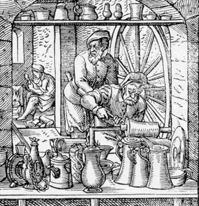
While pondering various lathe configurations, it occurred to me that a Great Wheel lathe would be good for demonstrating man-powered lathes. While spring-poles were predominant in woodturning, they also require some experience before one can be productive. A Great Wheel, operated by an untrained assistant, provides the advantages of continuous rotation (and continuous power), easily adjusted torque, and simplicity. In the 16th century, they appear to have been used predominantly by metal workers such as bell founders and pewterers. For their purposes, the high speeds and torque were ideal for finishing metal surfaces.
Unlike a flywheel lathe, which requires bearings for both the wheel and the drive head, the Great Wheel drive cord can be connected directly to the workpiece (a la a spring pole). With only one bearing to worry about, the engineering is much simplier. Of course, a disadvantage of a Great Wheel is that they are, well, Great. As illustrated in the 16th century, they are usually mounted to a wall and are some 6 or 8 feet in diameter. For a portable version, it would need to be a "not-so-Great" wheel that could easily be transported to events. I expected to build a wheel 18 to 24 inches; large enough to provide some speed, but small enough to be portable.
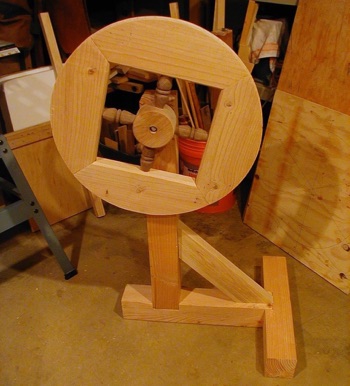
I had recently had some practice in wheel making while making a reconstruction wheel barrow, so I decided to make a simplified version of that wheel. I wanted a spoked wheel, but you could easily simplify the process by making a solid wheel instead. Instead of six fellies and spokes, I used only four, and I simply butted and glued the fellies together rather than lapping them. The wheel carries very little stress, so this seems adequate. A more authentic approach would be to mortise and tenon the fellies. I cut the channel for the drive cord using a gouge and a moulding plane.
My wheel is approximately 21 inches in diameter, with a solid hub of of 12-quarter birch. The fellies are cut from common 2x10 fir, and the spokes are turned from scraps of black walnut. The bearing is a bronze sleeve bearing (available at most home centers), which rides on an axel of steel roundstock (also available at the home center). I used stop-collars to hold the axel/wheel in place so that the wheel could be removed for transport. In retrospect, the outside end of the axel could have been peened into a head, removing one of the stop collars and giving it a less modern look. A washer and cotter pin might also perform the same function.
The frame for the wheel is simply common 4x4 stud lumber. When using it outdoors, I secure it in place with a couple of iron tent stakes. This allows me to adjust the drive cord tension simply by pushing or pulling on the lathe frame. If working inside, it helps to secure the wheel with weights braces, or ties to keep it securely in place.
In my research, I did find an illustration of a very similar wheel, purportedly of Roman origin, which mounts on an arm which pivots off the lathe frame. The advantage of this configuration is that the weight of the wheel will keep the tension on the drive cord. The disadvantage is that you must use a mandrel drive head as the drive cord will always be in the same place. I gave this a try, but the arm turned out to have too much sway and would not stay in line with the drive head. If I were building the lathe frame from scratch, this approach might work well, but as an add-on it wasn't practical, so I decided instead to use a standalone frame to hold the wheel.

Copyright 2009, Thomas Rettie.