Lathes Part 2:
Building a Flywheel Treadle Lathe
Lathes Part 2:
Building a Flywheel Treadle Lathe
Building and Shaping the Flywheel
I began with the flywheel, as it dictates the geometry of the frame. A good flywheel should be heavy, flat, and balanced. The exact size is not critical, but in general a larger flywheel will provide faster turning speeds and more inertia. One of Underhill's methods for constructing a flywheel is to glue/nail up three layers of board stock, staggering the joints by 45 or 60 degrees. This will not only give you a good thickness, but will also give dimensional stability (it will tend to remain flat). Cutting a circle out of something this thick isn't easy, especially when using hand tools, but it is still considerably easier than the alternative, which is to build a spoked flywheel.
When making your flywheel, it is very important not to lose track of its exact center. You will need to know this point to bore the holes for the bearings/axle. If you use a bandsaw and jig to cut the wheel, make the hole for the center as small as possible so you have an accurate reference (it's hard to enlarge holes accurately).
There needs to be a channel around the circumference of the wheel to hold the drive cord. You can either cut this by hand with a carving gouge, or wait until the wheel is mounted to the treadle and cut it with a turning gouge or bowl scraper.
Building the Frame
If you're not interested in toting your lathe about, a heavy, rigid frame is desirable. I built mine from pine, fir, and hemlock, which is cheap (thus allowing for failed experiments), easy to work, and makes it very light for transport, but your finished lathe will be sturdier, more precise, and vibrate less if you use good quality, heavier, dimensionally stable stock. Similarly, I used lap joints and wooden bolts to make it easy to disassemble. If your lathe isn't going on the road, I recommend proper mortise-and-tenon joints, and depending on what historical period you are pursuing, sturdy fasteners such as glue and/or screws/bolts.
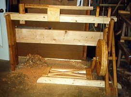
The initial prototype. While not terribly sturdy, it worked!
The exact construction of the frame is not important, but the dimensions should account for the following:
 The size of the drive wheel.
The desired working height.
The desired working length of the bed.
If you build the frame wider than about 18-19 inches between centers, you will also need to build a wider treadle (unless you have very long legs).
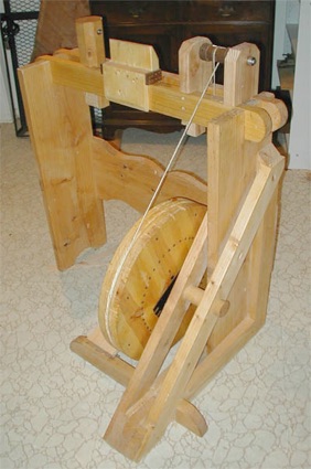
Front View of "Short" Working Version.
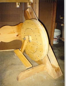
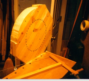
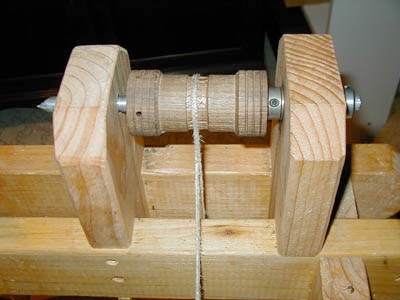
Detail of Flywheel.
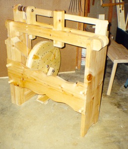
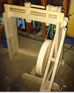
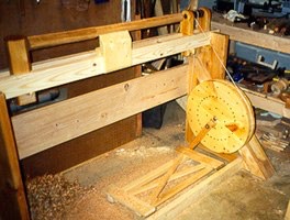
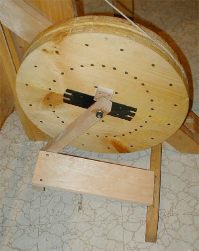
Back View. The addition of the stretcher greatly strengthened the frame.
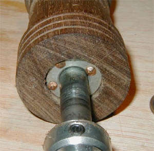
Mounting the Flywheel
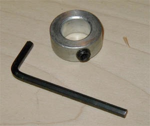
There are several types of bearings you can use for the flywheel, but you definitely do not want it resting directly on the axle; the metal-on-wood contact will eventually wear a larger and larger hole and throw the wheel off center. Sleeve bearings and ball bearings are readily available in most hardware stores. The flywheel is then held on to the axle with a third stop collar. This collar should be set loosely enough that the flywheel turns freely.
Building the Treadle
In most flywheel lathes of later periods, the foot treadle connects to a crank which in turn powers the flywheel's drive shaft. To simplify construction, Underhill's design connects the treadle arm directly to the face of the flywheel. This allows the axle to remain fixed, with the flywheel turning freely about it, and eliminates the need to fabricate a crank for the axle.
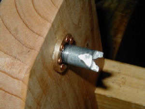
In my design, I used cut-off 1/4-inch lag bolts to make the upper and lower attachment pins for the treadle arm. For the upper attachment pin, the head of the bolt is counter-sunk on the opposite face of the wheel, the bolt is cut off before the threads start, and a 3/4-inch wooden block on the near face keeps the treadle arm from coming in contact with the axle.
The treadle itself is simply a piece of 3/4-inch board stock that is hinged to the treadle strut. I used a removable pin hinge so that it can be removed for transport. Attached to the bottom end of the treadle is a wood block that receives the lower attachment pin. The pin is simply another lag bolt, screwed into the block and with the head cut off.
The treadle arm is simply a piece of square stock with 1/4-inch holes in either end so that it can pivot on the upper and lower attachment pins. I did not bother with bearings in these attachment points, but you could for a more durable attachment. The treadle arm itself is held in place again with stop collars.
The Drive Head
Perhaps the most complex part of this project is the drive head. The flywheel will work fine even with a bit of wobble, but the drive head axle must be in perfect alignment with the centers or the piece being turned will wobble. For setting the axle bearings, even an old-tools purist may want to consider a drill press to get the holes aligned and true.
Another method is to work one end of the round stock into a blade. This gives a larger spur with more bite, but if you're not accustomed to working steel it can be more challenging. However you form the spur, make sure it is aligned with the long axis so whatever you mount to it will turn around a single point.
Treadle Lathe Overhaul & Lessons Learned
About 5 years ago, I built a flywheel treadle lathe "prototype," which because it worked, was never upgraded to a "production" model. It has served well, but it's gotten to the point where some poor materials and design decisions now have to be corrected to keep it in working order.
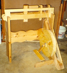
"Long" Working Version. Note buildout of rails, stretcher, and treadle. Also note moveable tool rest.
Flywheel
The flywheel is built up from three layers of boards. While not perfectly dead flat, it's close enough to get the job done. The chief problem with the flywheel is in the bearings. My original design used bronze sleeve bearings, which work very well but present a problem when used with a wooden wheel. If the bearings bind up at all, the flywheel will turn around the bearings, instead of the bearings turning on the axle. My attempts to set the bearings were only temporarily successful, and eventually the wood around the bearings became compressed and the bearings loosened. This led to a bad wobble in the wheel and a lot of wasted energy. I assumed I would need to build a new wheel to get it working again.
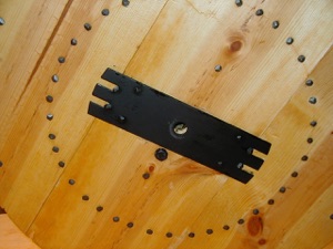
The results was very satisfactory. In fact, the wheel is now closer to true than it was when I first built it. The plates come with a shiny japanned finish, so I put on a coat of flat black paint to give them a more suitable look. A new wheel would still be nice, but this one should continue to work for some time.
Head Stock
The first step was to make new poppets. The important aspects are that they fit snugly between the bed rails, and sit perpendicular to them. I made this set wider, as wide as the bed rails, to give them more contact area. I then used the tail stock to mark the axis for the drive head. A drill press is very helpful in boring the holes.
For new bearings, I decided to go with face bearings instead of the sleeve bearings I used before. This greatly cuts down on the friction and is a bit more tolerant of any minor misalignment between them.
Treadle
Additional Sources on Lathe Construction
Abbott, Mike. Green Woodwork. Guild of Master Craftsman Publications, Ltd, Lewes, East Sussex, 1989. Extensive discussions of building and using springpole lathes.
Bealer, Alex W. Old Ways of Working Wood. Bonanza Books, New York, 1980. Appendix on both a pole lathe and flywheel lathe.
Underhill, Roy. The Woodwright's Eclectic Workshop. University of North Carolina Press, Chapel Hill, 1991. Includes illustrations of an 18th century folding lathe.
Underhill, Roy. The Woodwright's Workbook. University of North Carolina Press, Chapel Hill, 1986. Discussions of bow-spring lathes, spring pole lathes, and flywheel lathes.
Copyright 2009, Thomas Rettie.